#
Step 5: Elastoplastic Analysis
#
Load combination
Edit load combination:
- In the LOADS tab in the ribbon choose Load comb__inations.
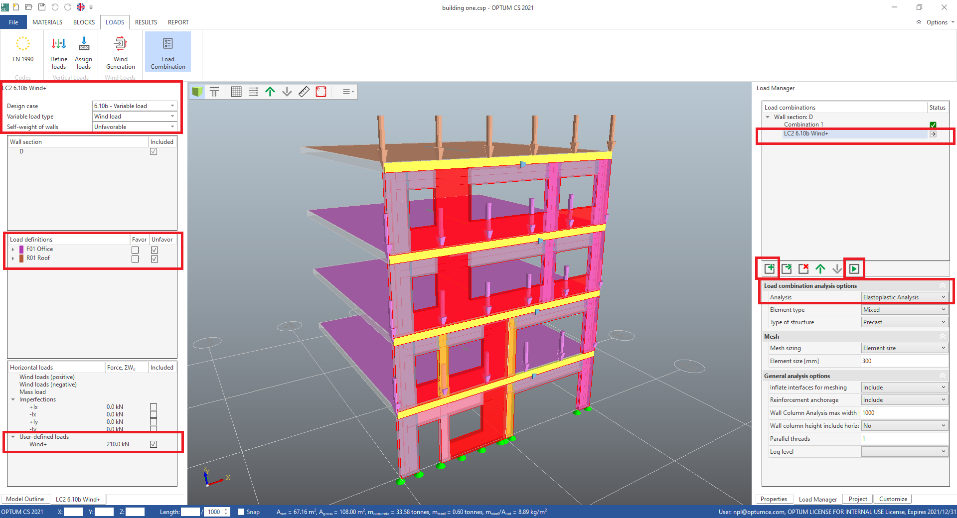
- In Load combination analysis options in the Load Manager change Analysis to Elastoplastic Analysis for Combination 1.
Add a new load combination for the wall section:
- In the load manager, add another load combination by pressing the Add a new load combination button.
- Double click the name of the new load combination to rename it. Name it "LC2 6.10b Wind+".
- In Load combination analysis options change Analysis to Elastoplastic Analysis.
- In the settings for the load combination on left hand side, change Design case to 6.10b - Variable load.
- Also change Variable load type to Wind load and Self-weight of walls to Unfavorable.
- In Load definitions include the two load definitions as Unfavorable.
- In Horizontal loads include the user-defined load Wind+.
- Press Run analysis (F5).
- When the analysis is done, close the Analysis Progress window. The RESULTS tab is now active.
#
Elastoplastic analysis result
The elastoplastic analysis results in different types of results; Direct results from the finite element analysis and post processed code check results. Also the input parameters for the calculation can be illustrated.
#
Finite element results
#
Displacements
- Select Combination 1 in the load manager.
In the RESULTS tab, the displacement plot "Panel |U|" is displayed. This is the actual in-plane displacement. Elastoplastic behaviour of the concrete and reinforcement is taken into account in this calculation, making the result very accurate, compared to a linear elastic calculation.
- Add a check mark in the Show displacement box in the ribbon, and adjust the scaling using the mouse wheel while the cursor is on the scale input field, to show the wall section in deformed shape.
- Select the other load combination in the load manager and check if the displacement corresponds to the direction of the applied horizontal loads.

#
Stresses
In Stresses in the Panel section in the ribbon, select "Panel σc2", the minimum of the principal stresses in the concrete (the (absolute) highest compression stresses in the concrete). The biggest compression is in this case 10.7 MPa, as displayed in the colour bar in the scale section in the ribbon, which is the maximum allowable compression stress in the elastoplastic finite element calculation:
σ = ν · fck / γc = 0.5 · 30 MPa / 1.40 = 10.7 MPa
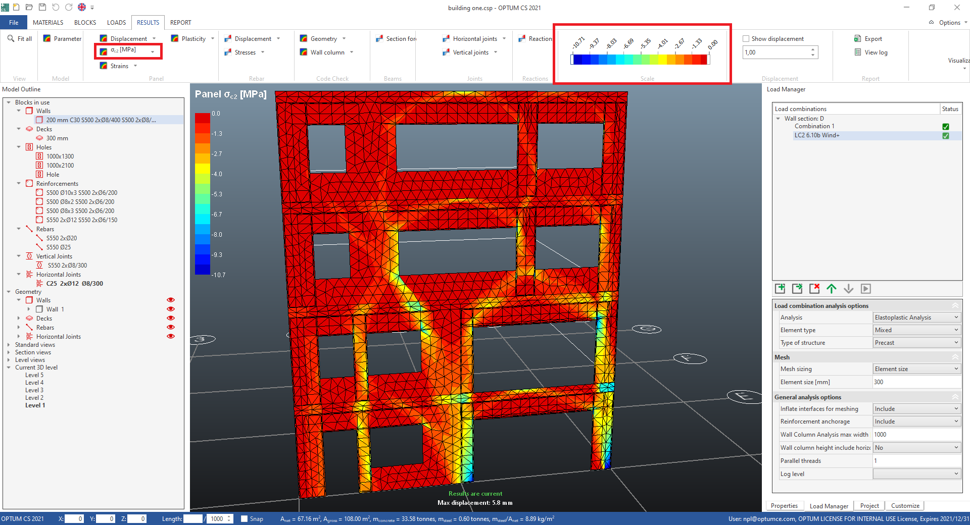
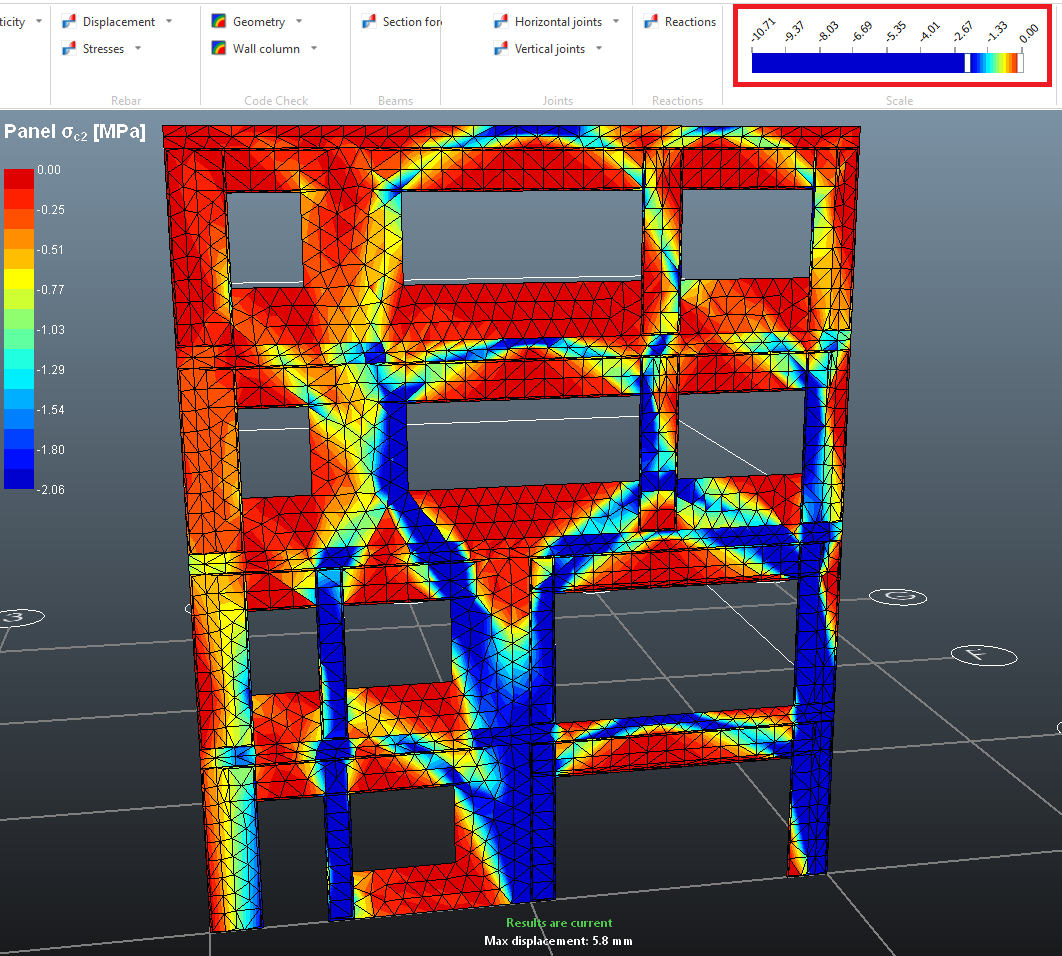
- Drag the left limit in the Scale bar in the ribbon to the center or even higher, to intensify the compression struts/paths in the wall section.
Explore many other results of the finite element calculation in the Panel, Rebar, Joints and Reactions sections in the ribbon. The input parameters for the calculation is grouped in the Model section in the ribbon. This is a great tool for visual control of the model inputs.
#
Code check results
Code check includes calculations of walls and beams. The results are made in the post processing, after the FE calculations, in compliance with EN 1992 (EC2), and with similarities to the analyses used in the calculation software provided by the danish concrete element association, Betonelement-Foreningen. The panels in the wall section are divided into slices, and for each of these a second order analysis is performed, checking the stability and the out of plane displacement. Also the wall beams are recognized and analysed. In the RESULTS tab, the results are presented visually. More details, including the NM-curves, tables and summarizing plots are available in the report, which is explained in the next step of the tutorial.
#
Wall slice utilization
The utilization of the wall slices are visualized for each load combination in the "Code Check M0Ed/M0Rd" plot in the Wall column menu in the Code check section in the ribbon.
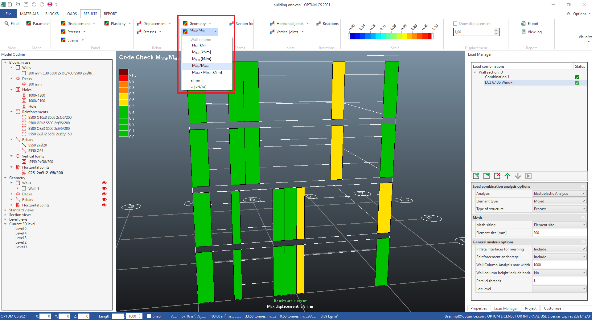
Explore more results in the Code check menu and calculated input parameters in the Geometry menu.
#
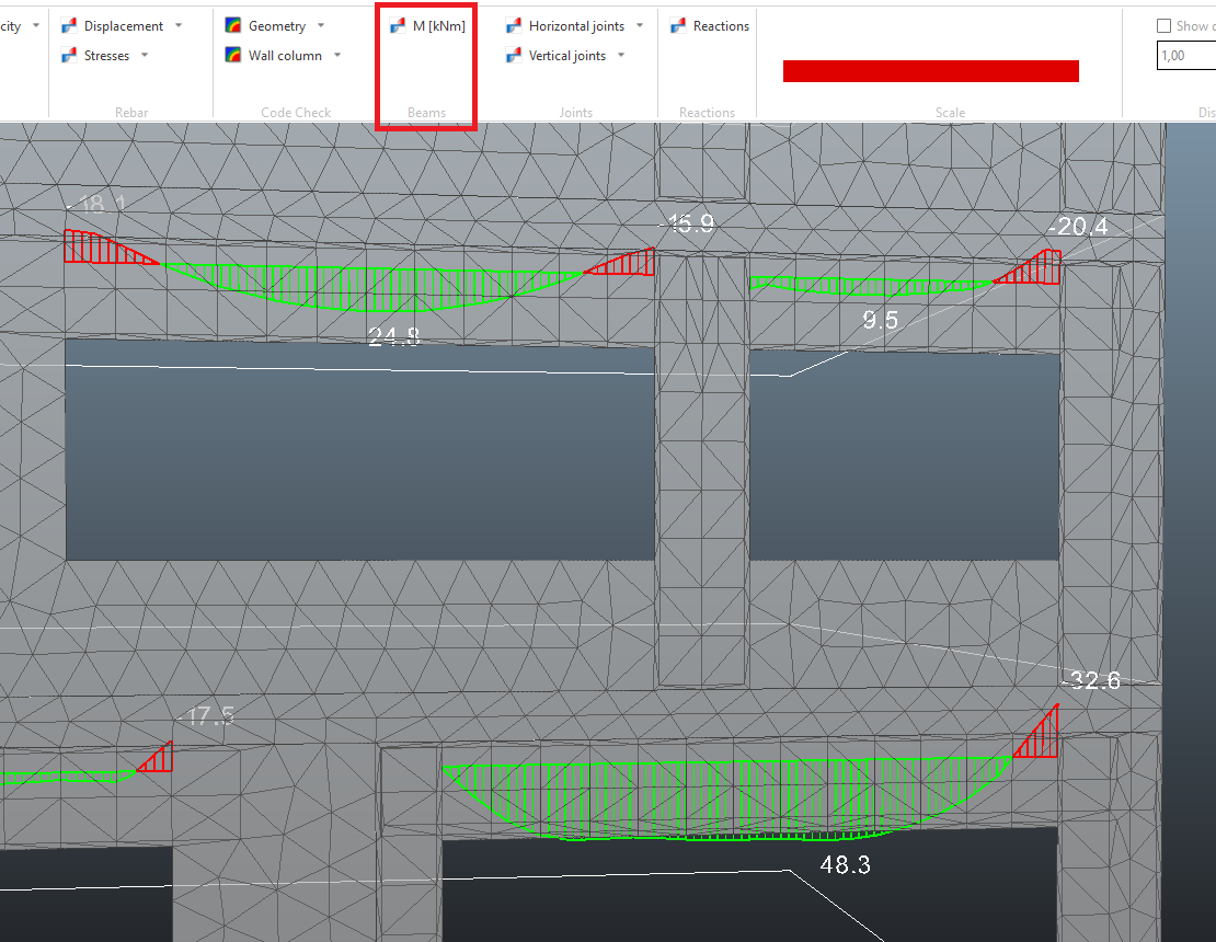
Beam moment
The internal moment for the beams are visualized for each load combination in the "Beams M" plot in the Section forces menu in the Beams section in the ribbon. Also the other section force plots are available in this menu. The horizontal joint is included in the calculation of section forces.
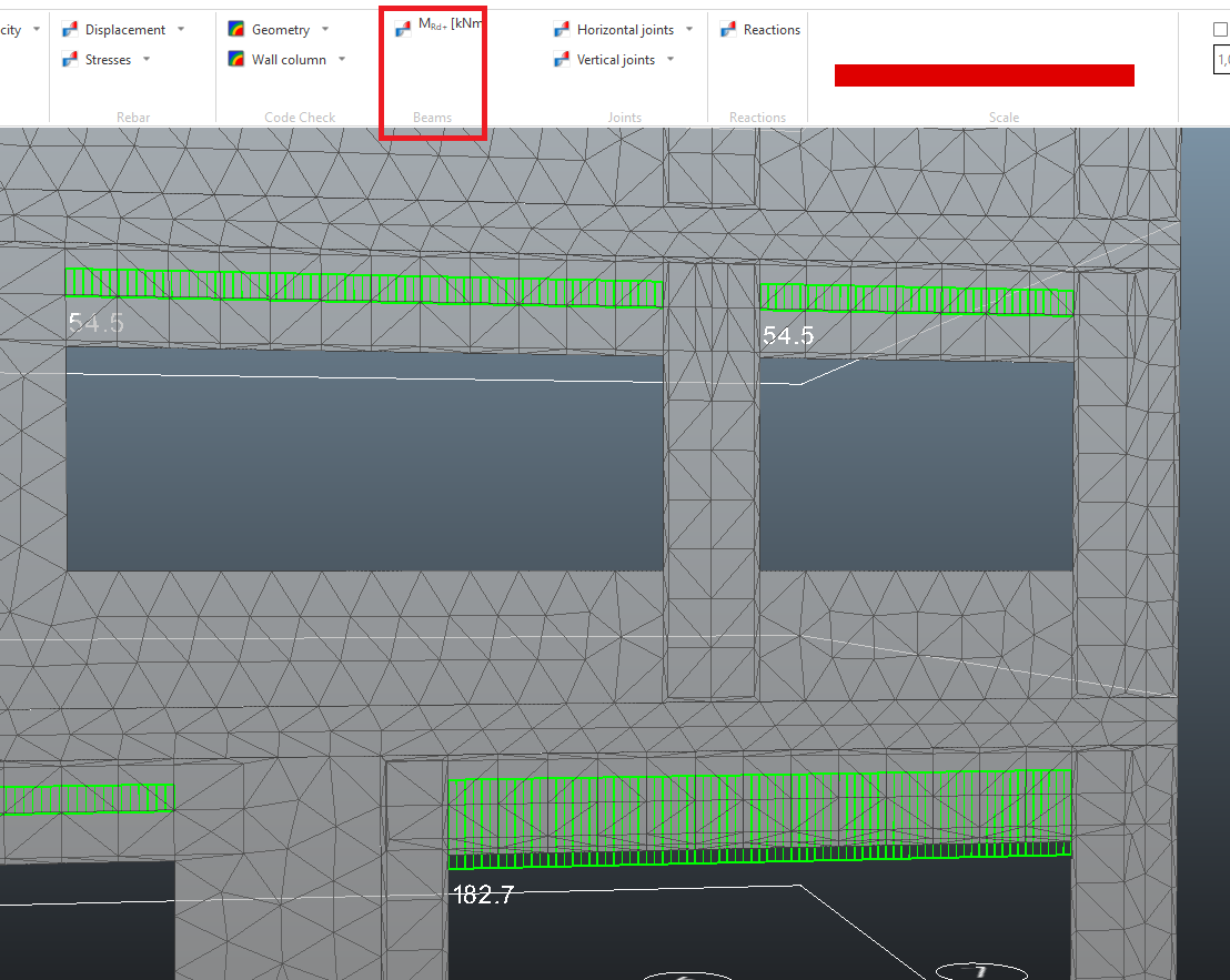
The positive and negative moment bearing capacity plots, MRd+ and MRd- are available in the Section forces menu, displaying the capacities calculated at mid beam, with no normal force, and without including the horizontal joint.
Next step is generating a report.