#
Step 1: Gemoetry
#
Overview
In OPTUM CS the model is described through different types of blocks. Each block is used for several geometries. A block includes e.g. the concrete and steel material parameters, the reinforcement arrangement and other parameters.
#
Walls
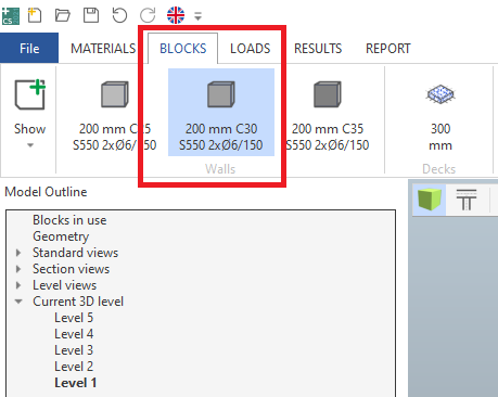
Create a wall:
- Choose the wall block named "200 mm C30 S550 2xØ6/150" from the BLOCKS tab in the ribbon, by clicking it.
- Create a wall by clicking two grid line intersections, D/4 and D/6.
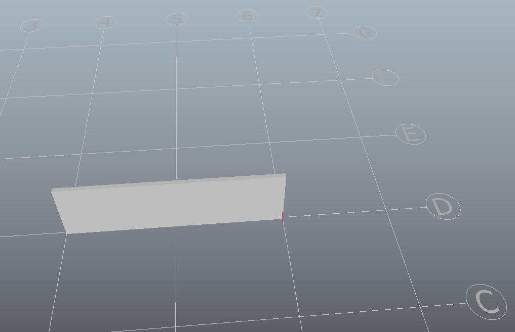
- Press ESC to leave the tool.
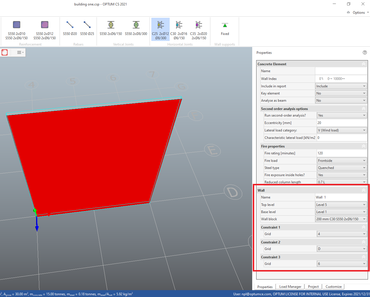
Edit the wall:
- Select the wall by clicking the wall geometry.
- In the Properties pane, locate properties related to the Wall and change Top level to Level 5.
#
Decks
In OPTUM CS Decks distribute vertical loads to the surrounding walls and create horizontal joints where they intersect with walls. Create decks:
- Choose the deck block named "300 mm" from the BLOCKS tab in the ribbon.
- Move up one level using the green arrow in the left top corner of the canvas.
- Create a deck by clicking two grid line intersections, D/4 and F/6.
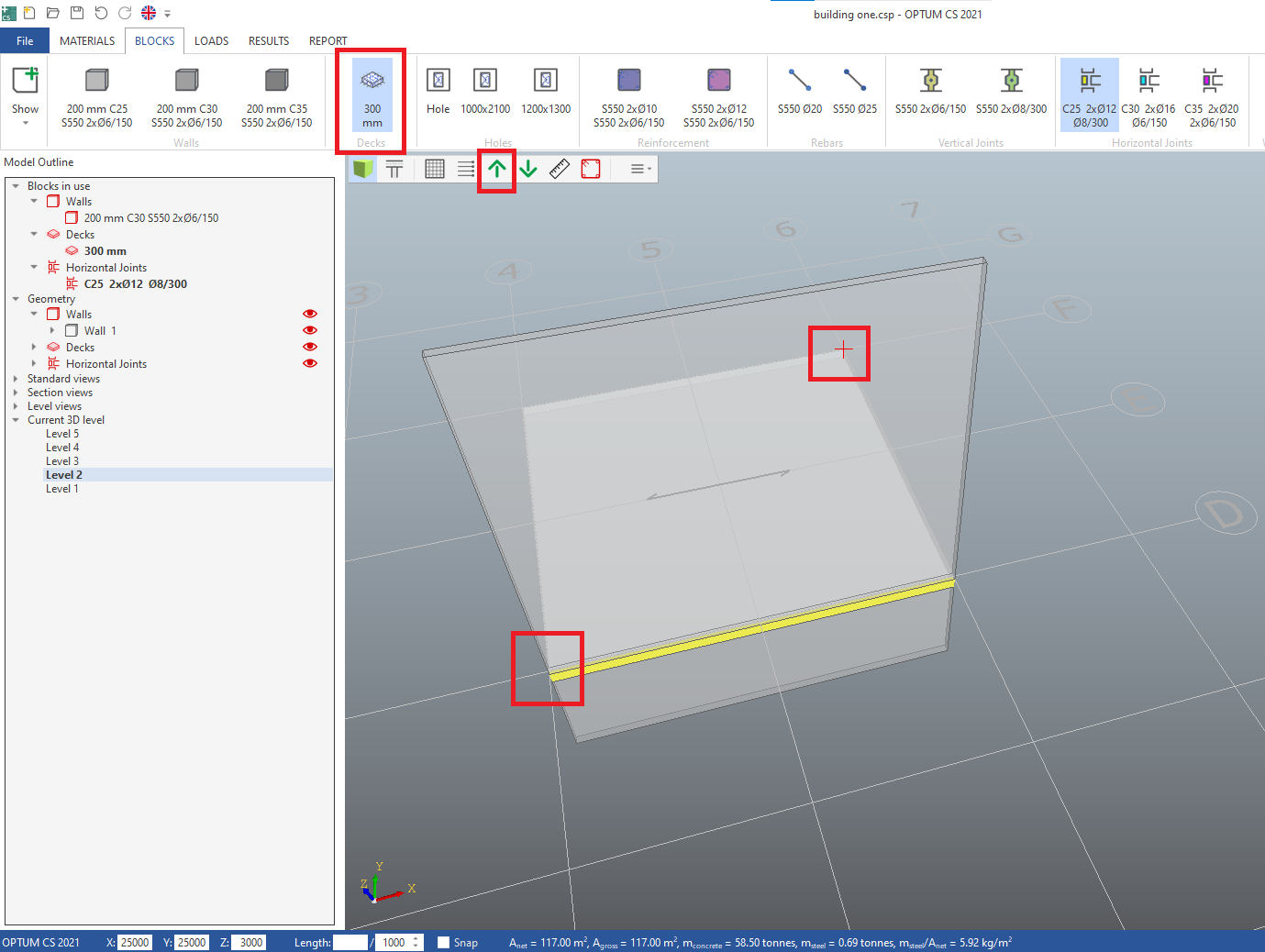
- Press ESC to leave the tool.
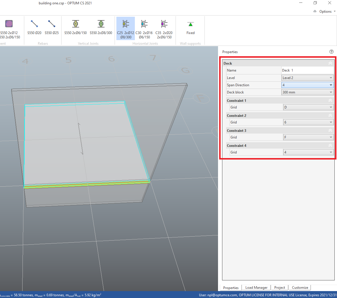
Edit deck:
- Select the deck geometry. Use TAB to cycle through objects at cursor.
- In the deck properties change Span Direction to 4.
- Select the deck, press Ctrl + c to begin copying,
- click grid line intersection D/4, move up one level (use keypad plus "+"),
- press Ctrl + v to begin pasting,
- click grid line intersection D/4,
- move up one level,
- paste again by clicking and
- continue until all levels have decks.
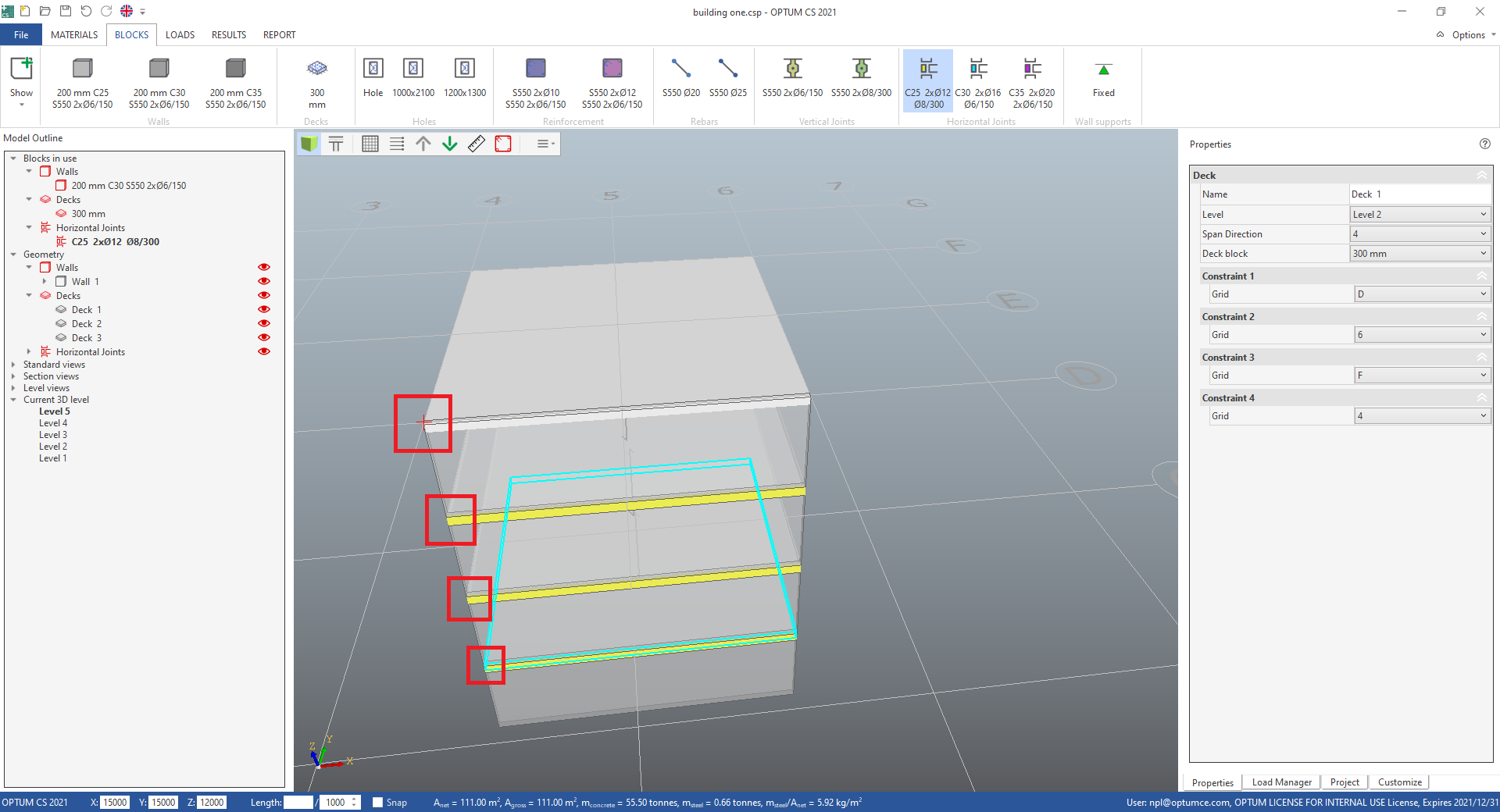
- Press ESC to leave the tool.
#
Holes
- Choose the hole block named "1000x2100" from the BLOCKS tab in the ribbon.
Create a hole by clicking two points on the wall geometry:
- First the insertion point
- then a point in one of the four quadrants around the insertion point to choose the relative position.
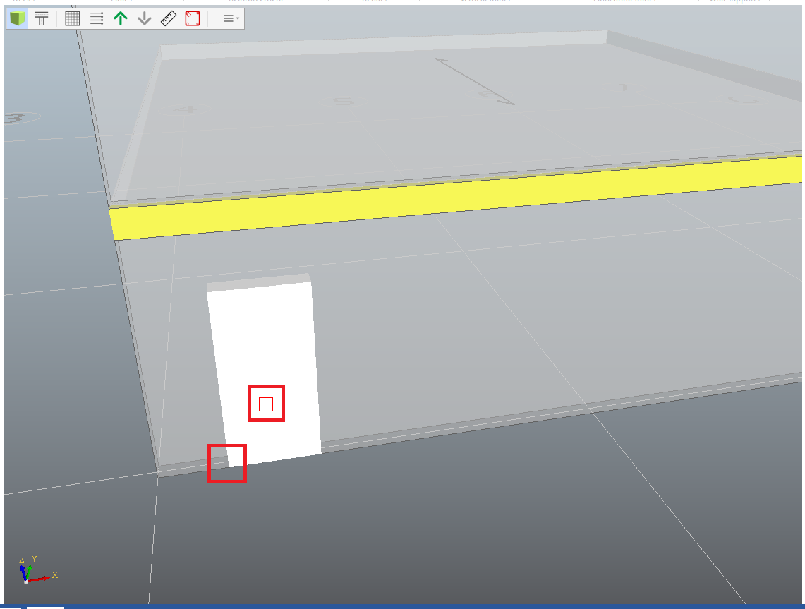
- Press ESC to leave the tool.
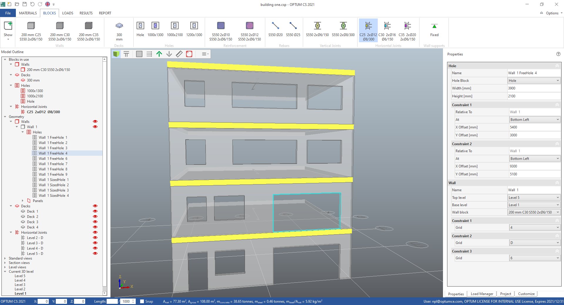
Edit the hole:
- Select the hole geometry.
- In the hole properties change X Offset [mm] to 800 to move the hole 800 mm away from the edge of the wall.
Create a new hole block:
- Right click the hole block named "1000x2100" and
- choose Clone in the pop up menu.
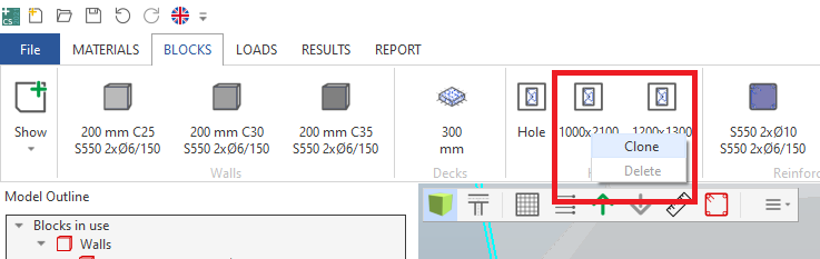
- In the sized hole properties for the new hole block change Height [mm] to 1300.
Create a hole on the next level above the first hole:
- Move the cursor to the top left corner of the first hole,
- keep Alt key down to snap to vertical (or horizontal) auxiliary line,
- move cursor up,
- click to create insertion point,
- release Alt key,
- click second point to choose relative position and insert hole.
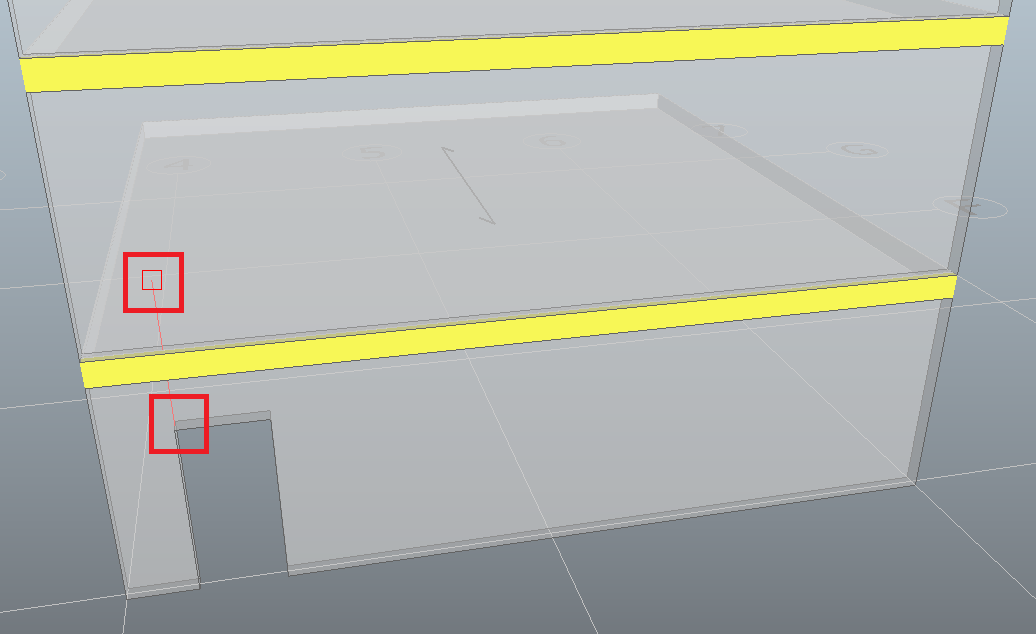
- Press ESC to leave the tool.
Edit the hole:
- Select the new hole geometry.
- In the hole properties change Y Offset [mm] to 3_800_ to move the hole to a position 3800 mm above the bottom of the wall.
Create freely sized holes on the wall using the hole block named "Hole". Try to make the wall elevation look like the one in the next illustration. Try to make use of snap and copy-paste. Copy-paste multiple holes by pressing the Shift key to select several holes.
#
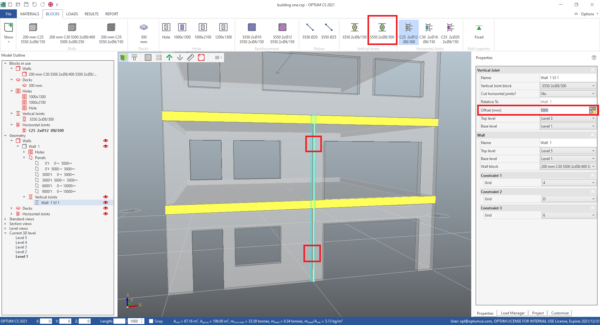
Vertical joints
- Choose the vertical joint block named "S550 2xØ8/300" from the BLOCKS tab in the ribbon.
Create a vertical joint by clicking two points on the wall geometry:
- First a point on level 1,
- then a point on level 2.
The wall now contains four concrete elements.
- Press ESC to leave the tool.
To edit the position on the wall, select the vertical joint geometry, locate the properties related to the vertical joint and change Offset [mm].